Our coach left the Coach and Four (former New Inn) in Wilmslow at 11:00 for a lunchtime arrival in Derby, where Rolls Royce provided us a light sandwich lunch. Over Lunch, Andrew Davies, Deputy Chief Financial Officer for Civil Aerospace and Finance Director for Civil Operations gave us an overview presentation of Rolls Royce business directions. This was followed by a technology presentation by Mike Whitehead, Engineering Technology Director.
Mike's fascinating talk was on future engine technology, which for as far ahead as one can see will be gas turbine based as no other power source has anything like the power capability for the weight and size of power unit needed in aerospace use. We won't be seeing electric airliners for a very long time yet, if ever. A modern turbofan airliner could power a city, such is the energy they generate. As an example of the level of technology in today's turbofan engines, he mentioned that a single turbine blade in such an engine is smaller than the human thumb, sits in a gas flow where temperatures are similar to the surface of the Sun (many times the melting point of the metal the blade is made of), and extracts from the gas flow more power than a Formula One car develops.
To prevent it melting, the blade is cooled by a cooling system that could keep an ice cube firmly hard frozen in a domestic gas oven at gas mark 9.

RR Trent conventional 3-shaft engine. Note how the casing for the low pressure fan turbine at the back of the engine restricts the thrust-producing bypass air flow from the fan.
But the big upcoming development in gas turbine technology is the Ultra Fan. Conventional Rolls Royce engines are 3-shaft: that is, there are 3 concentric shafts running the length of the engine's centre. The outer one connects the high speed turbine to the high speed section of the compressor, the intermediate one does the same with the intermediate turbine and compressor, and the inner one connects the fan turbine to the thrust fan on the front of the engine. The high speed turbine runs the fastest and is a relatively small diameter, and the fan turbine runs the slowest and is of a large diameter. All 3 shafts are free to run speeds which produce optimum efficiency, but the shaft driving the fan has to run at a compromise speed. Also, its large diameter turbine case causes unwanted constriction to the bypass air duct (this can be seen in the picture of the Trent engine above).
The compromise of the turbine driven fan is that the engine designer wants the turbine to run at as fast a speed as possible for more efficiency and smaller size (less weight and less constricting of the bypass duct). He wants the fan, however to run as slowly as possible so it can be larger to move a bigger volume of air, with as much of the fan as possible remaining subsonic for best thrust efficiency and quieter running (the buzz-saw whine you hear from a Turbofan engine at high power comes from the shock waves generated as the fan blades go supersonic).
The Ultra Fan uses a gear box. It does away with the fan turbine and the fan drive shaft, making the engine 2-shaft, not 3. Instead of being driven by its own turbine, the fan is driven through an epicyclic reduction gearbox with a ratio of 3.8 to 1, from the intermediate shaft. This gear box has to be around 97% efficient (pretty much unknown for gear boxes up to now) to reduce excess heat generation, it has to transmit up to 100,000 hp, and it has to weigh no more than a ton. Rolls Royce have built a plant in Dahlewitz, Germany, to build and test the gearbox. Use of the gearbox allows the fan to be of larger diameter (so it shifts more air) and running more slowly than on current generation engines, with just the fan tips being transonic, and non of the fan operating in the supersonic range.
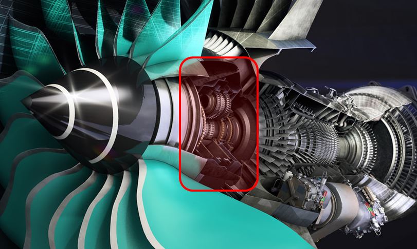
Ultra Fan gear box replaces the LP turbine and fan drive shaft
Some of the challenges faced in developing the gearbox were explained. For instance the gear teeth are accurate to about 3 microns (a human hair is about 75 microns diameter). However, the forces the teeth are transmitting and the centrifugal forces due to the planetary gears' high speed rotation distort the gears by up to 100 microns in use.
It might seem obvious that gear oil would be used to lubricate the gear box, but that was found to be to viscous, and also carcinogenic; not good when one considers the gearbox runs so fast that it cannot use conventional seals. Instead, air seals are used which means (since compressed air from the engines is used to pressurise the passenger cabin) minute amounts of this oil may be present in the cabin air.
It might seem obvious that gear oil would be used to lubricate the gear box, but that was found to be to viscous, and also carcinogenic; not good when one considers the gearbox runs so fast that it cannot use conventional seals. Instead, air seals are used which means (since compressed air from the engines is used to pressurise the passenger cabin) minute amounts of this oil may be present in the cabin air.
Instead, the gearbox is lubricated by engine oil, whose main jobs are to prevent metal to metal contact of the gear teeth, and to carry away the heat (the gearbox runs at about 80 degrees Centigrade and must be cooled - not easy if the aeroplane is taking off at perhaps Dubai with a 50 degree ambient air temperature).
A final thought on this remarkable gear box; each pair of teeth transmit more power than an entire grid of Formula One race cars - about 20,000 hp.
-----------------------------
We re-boarded our coach for the short trip to the Rolls Royce Trust Heritage Centre, where volunteer guides Tony Ruff and John Plant showed us around.

Rolls Royce's first commercial 3-shaft engine, the RB 211. Note the straight fan blades with strengthening ring at about half blade span. This engine was originally designed with a carbon fibre composite fan, which proved too fragile (failed bird strike tests). Launch customer Lockheed planned to put it into the L-1011 TriStar, but the failure of the RB 211 bankrupted Rolls Royce.
The government rescued Rolls Royce, a titanium fan was developed, and Lockheed got their engines.

The prototype 3-shaft engine, developed for a Fairchild aircraft that didn't make it to production

A closer view of the straight fan blades and strengthening ring

A demo RR Merlin engine mounted on a trailer, here showing the control panel

The next generation of RB 211 engine had wider chord, curved, fan blades and no longer required the strengthening ring. Another innovation is the rubber tip on the fan spinner (being pointed out here). Previously, complex hot air or electric heaters were used to prevent ice forming in the tip of the spinner (ice forming here could build up and then break off, being sucked into the engine causing damage). The rubber tip is a far simpler solution; as the ice begins to form the tip becomes unbalanced and wobbles, and the ice breaks off before it has chance to accumulate to a dangerous size.

Latest fan blade shape, here on the Trent 900

The first production Rolls Royce jet engine, the Welland (with a cowled Griffon piston in the background)

One of Rolls' most successful engine, the Dart turboprop. Used on the Viscount, Fokker F27, Argosy, and HS 748 among many other aircraft, it has a dual centrifugal compressor which gave it its characteristic whistle.

This isn't a RR engine, it's a de Havilland Ghost engine as fitted to the Comet 1. The Comet 1 suffered some tragic crashes caused by metal fatigue. This was exacerbated by the airframe being built of thin aluminium to save weight, as the Ghost engine had insufficient power for an airframe of conventional weight.
The Comet re-appeared as the Comet 4, powered by RR Avon engines. Its technical problems were behind it, but by then the American Boeing 707 had taken the market.
Many thanks to Luke Logan, Andrew Davies, and Mike Whitehead for giving us their time today, and to Tony and John for hosting us at the RR Trust Heritage Centre.
.
No comments:
Post a Comment